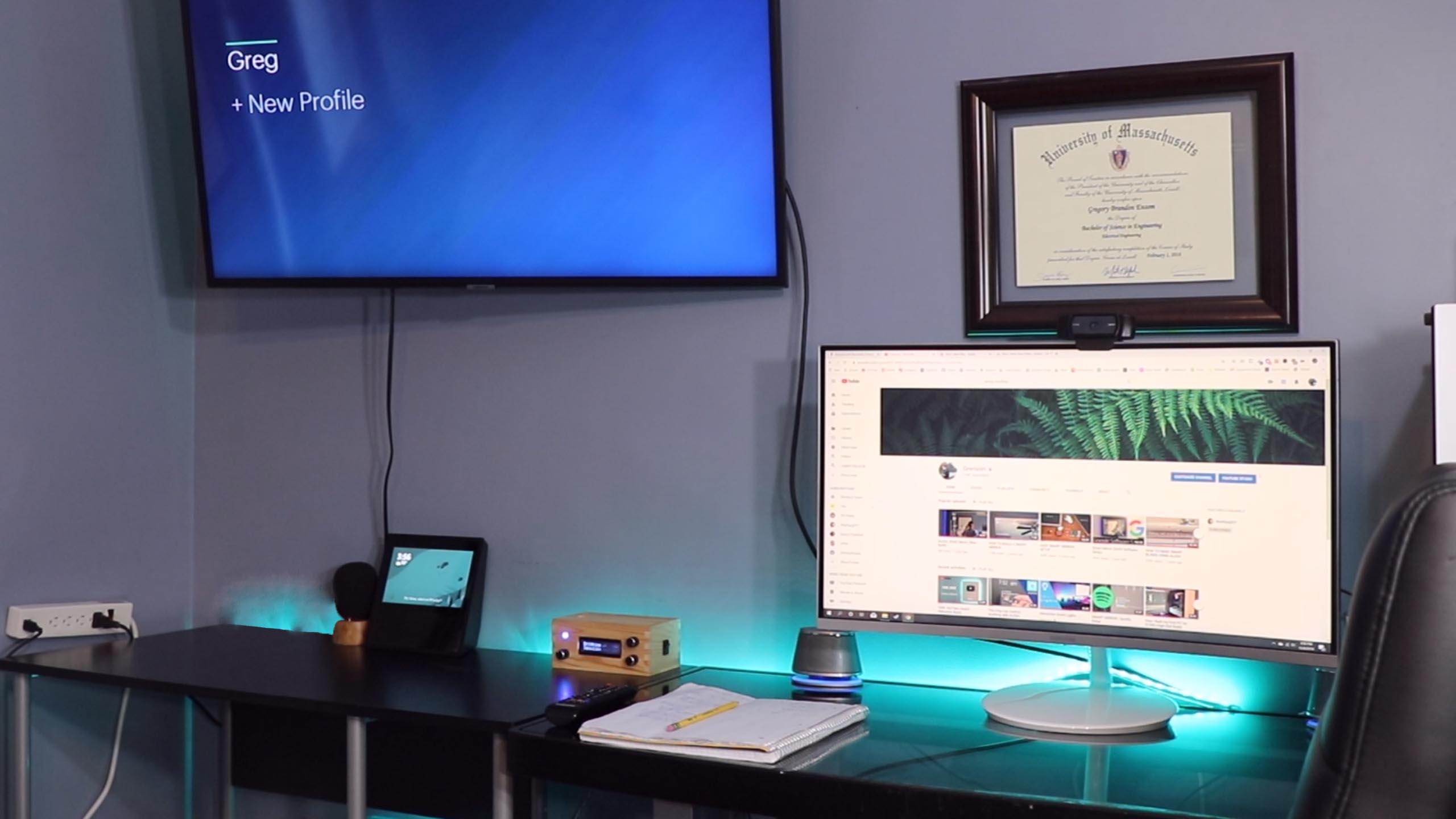
Interactive Smart Lights
Alexa Enabled (optional)The Interactive LEDs consist of the WS2811 Led Strip and an Arduino with Sound Sensor. The sound sensor can sense frequencies and convert the signal into a color spectrum through Logic done in the Arduino ATMEGA microcontroller. You can find full schematics and programming on my Github Repository linked on this page
Skills
- C Program
- Schematics
- Soldering
Instructions
Below you can find a list of the parts, schematics and programming needed to allow you to recreate and produce this project.
Parts Needed
Hardware Components
1
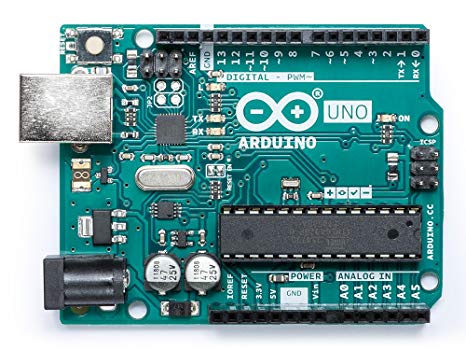
Arduino Uno
This is used to write the logic that all the controls and sensors interact with the LED strip. This must be powered by 5-12VDC
2
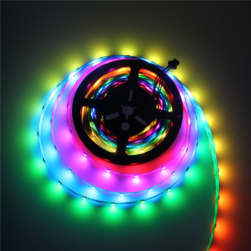
LED Strip
The WS2812B RGB LED Strip Light is individually addressable using the Arduino Uno and get turn any color of the spectrum using the RGB color codes.
3
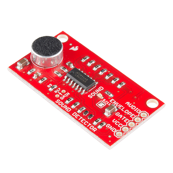
Sound Module
This transducer sound module converts sound vibration into an electrical signal that can be measured raw or through an analyzing envelope.
4
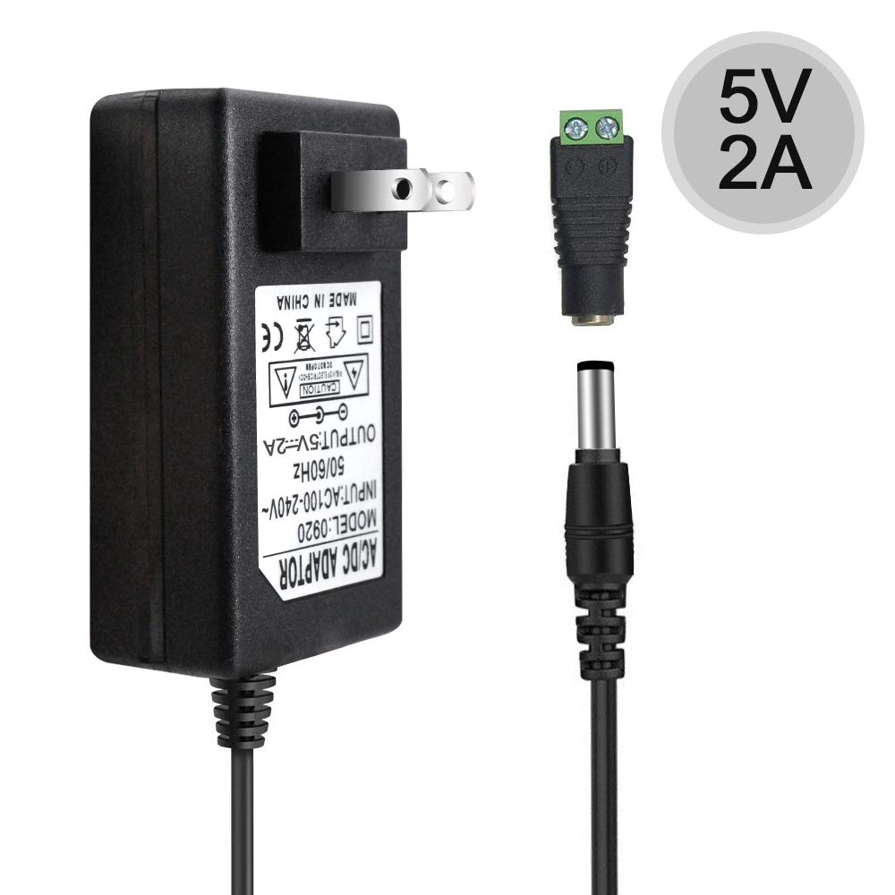
5V Power Supply
This 5V power supply is capable of outputting up to 2 Amps which is more than enough for the Arduino Uno and 10ft long LED strip. It also comes with a barrel adapter for custom wiring.
5
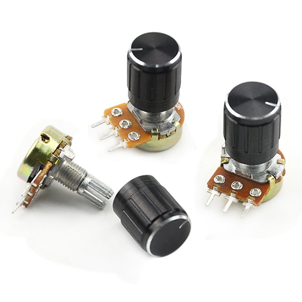
Potentiometer / Knobs
(OPTIONAL) These potentiometers give a variable voltage back to the arduino in the form of turn the knob CW and CCW. These are used to determine brightness, sensitivity and color change in the LEDs.
Schematics
Schematics
Below I list exactly how to hookup your Interactive LEDs with the parts listed:
1. Arduino Uno
Everything uses the Arduino as the main controller. See the schematic or go to my GitHub to see full schematic.
2. RGB LED Strip
The LED strip has three wires: 12VDC[Red +], 0V/GND[White -], Data Pin[Green]. The green Data wire goes to an Analog Output from the Arduino
3. Potentiometers
The potentiometers control settings and are powered by 5V from the Arduino and run thier signal into Analog Inputs on the Arduino. They are just turn knobs. They are for: Brightness, Sensitivity and Mode Setting.
Programming
Download the LED-Audio-Spectrum Repository:
To find all the code and setup instructions you can visit Grensom on github.com. You can find the specific repository here for the Interactive LED Project
Download Program (.ino) onto Arduino using Arduino IDE.
- Install Library: Arduino IDE >> Sketch >> Include Library >> Manage Libraries >> "search for" FastLED
- Open Sketch (.ino)
- Upload to Arduino through USB Connection
Full Instructions
You can find the full Instructions on my GitHub Repository
Overview Instructions
Overview Instructions
- Download the LED-Audio-Spectrum Repository and Arduino IDE if you don't have it
- Open Arduino IDE and download the FastLED library. Arduino IDE >> Sketch >> Include Library >> Manage Libraries >> "search for" FastLED
- Connect Arduino Uno to computer via USB connection and Upload sketch(.ino file) to Arduino.
- Complete the Full Schematic with the Arduino, LED Lights and Potentiometers
- Connect 12V Power Supply to wall outlet and Enjoy